Fish Tank Solution Mixer v2
The second iteration of the mini-project, purpose built for mixing a vat of calcium carbonate solution. The device fits onto the lid of the vat, where a mixing head dips into the solution. A time interval for its sleep and mixint time can be set. For this iteraiton, the speed of the mixing and the method of mixing can also be set. These settings are also now saved even when the device is powered off.
Usage
Power: USB Micro B, at least 5V 200mA DC, USB from a common phone charger would suffice.
To turn on the device, simply plug in the USB. There is no power switching as a battery source is not included. When powered, the screen will turn on. Use the knob on the lid to select through the options:
- Sleep time: Time interval between mixes.
- Mix time: Length of time to mix.
- Mix speed: Rotational speed for mixing by adjusting the motor PWM.
- Mix mode: The rotation method for mixing.
Settings will be saved between power cycles, but will still need to click through all the options. Note that for sleep time, it will exactly be what was set by the user, unlike in v1 where the mix time was subtracted from the sleep time. The device will go into a mix mode right away, then go to sleep. The display will show a message while asleep.
The Problem
An alkaline solution of calcium carbonate is used for the operation of a tropical fish tank. However, the solution becomes saturated with extra particulates settling at the bottom.
Feedback from v1
The v1 solution mixer operated for about 3 months. It was reported that the motor had ceased to spin, but the device was still powered on. It was concluded that the mode of failure was the modified servo motor burning out. For the power, the user found it best to only use USB power and did not use battery power. Another point of concern was the timing of the sleep intervals, where using the Arduino’s internal timer was not accurate enough for both sleeping and mixing. A pilot light was desired as it was difficult to tell whether the device was powered on or not when asleep.
Design constraints
Learning from v1, the goal of this iteration were to address the issues encountered. The main design constraints from v1 still hold; mixing effectiveness, material choice, and power usage. However, power usage is not as big of a design consideration as this iteration was to be USB power only.
There are a few additional requirements for this iteration:
- Serviceability: The device should be easier to maintain/fix should something go wrong during its lifetime.
- Timing accuracy: A greater accuracy of sleep and mix intervals compared to v1.
- Overall Reliability: The user should be able to trust the devices operation through an indicaiton that it is working, and that the device will not break down.
Initial approaches
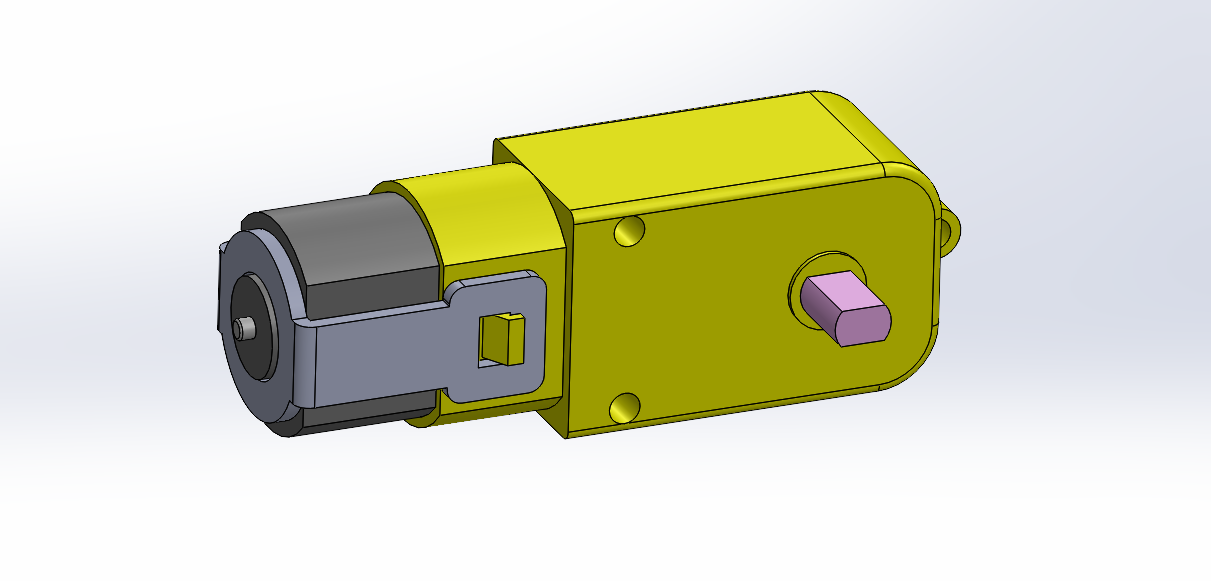
Building off the first iteration, the main components of a microcontroller, motor, display, rotary encoder, and USB power was be included. To satisfy the new requirements and feedback, a few changes were made. The motor was changed from a modified servo motor to a larger, more basic DC motor.
The arduino was changed to an Arduino Pro Mini for its smaller form factor

The motor used was that of a hobby toy motor, ubiquitous in DIY robot kits found online. It had the benefit of having a gear assembly included in the enclosure, all at a low price point.
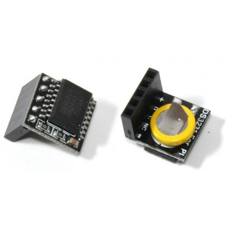
In addition to these changes, new modules were added. The first is the DS3231 real-time clock module. This module allows the device to keep an accurate time independent of the Arduino. It has the ability to wake up the arduino from a sleep state, saving power overall. The variant used for this device was one built for the Raspberry Pi, but is still the same IC.
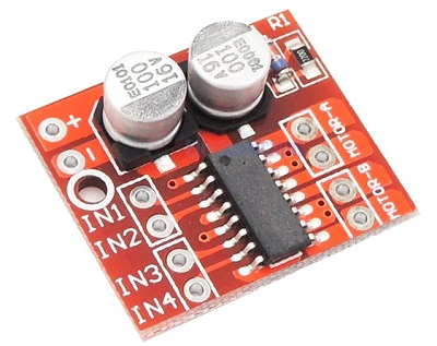
An H-bridge was implemented to control the new motor. This gives the ability to determine rotation direction and rotation speed through software.
Hardware
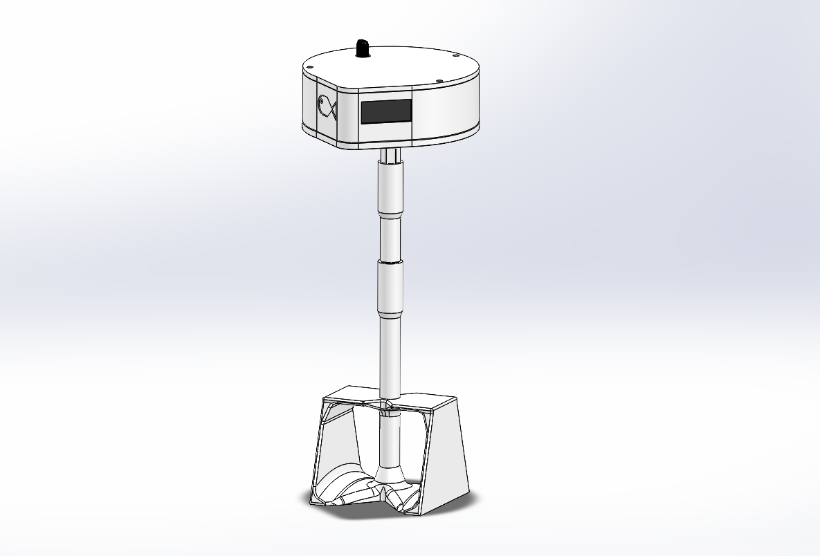
The most notable change in this iteration is the wider electronics housing. This was done to accomodate the new modules.
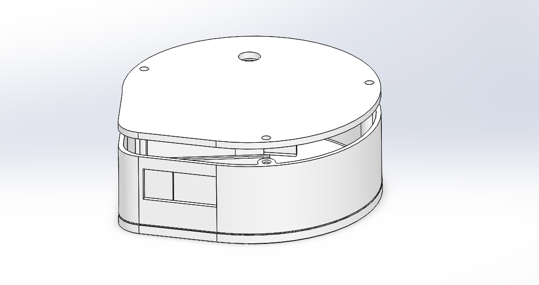
The external form of the enclosure has a lower height than v1, but utilizes the entire space over the lid of the solution tank. The USB port placement is in the same direction, but is right on the edge of the enclosure. The rotary encoder was also moved to the lid.
Internally, the layout of the components was made to maximize the available room for wiring. To secure components, walls made to friction fit between them.
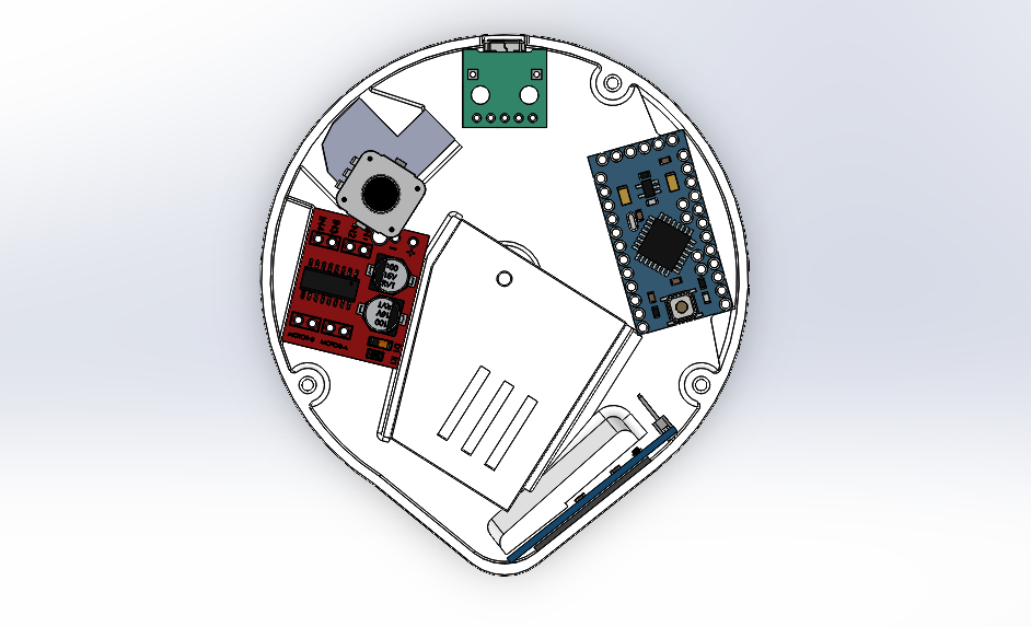
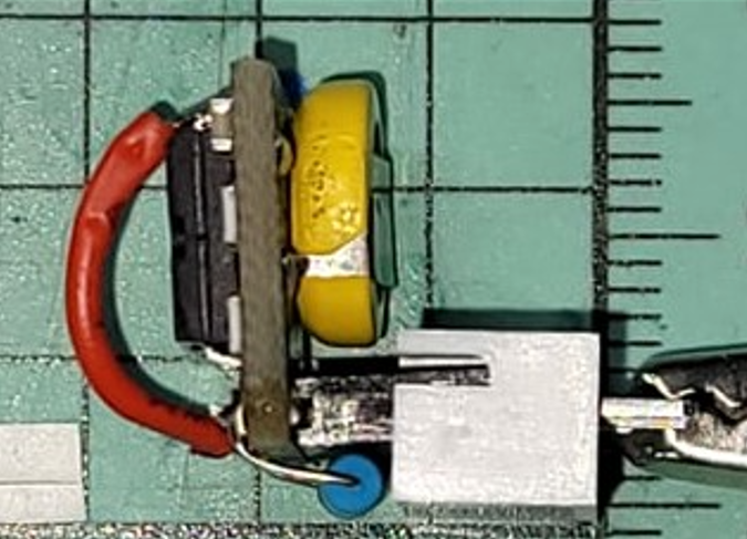
The USB port is attached to the lid near the top, and the Arduino is fitted beside it to the right. On the bottom right, the OLED display is fitted into a slot. Taking up the most space in the middle is the motor (not modeled) and gearbox. Left of that is the motor driver, and above that is the RTC (a placeholder model was used). Attached to the lid above the RTC is the rotary encoder/button. This arrangement allowed for a large volume between the gearbox, Arduino, and RTC to be used for wiring.
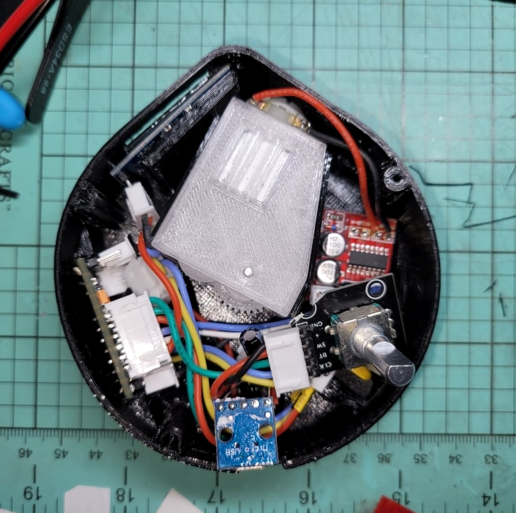
Here is an image of the actual layout:
The mixing head and shaft were also modified. The shaft was split into two versions: a 25mm + 50mm connecting shaft, and a full 75mm shaft. This was done by adopting a thicker connector between the shafts. The shortened shaft as created mainly to better package the device for shipment, as this iteration was much bulkier on its sides than v1.
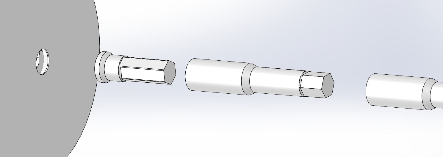
Because of the enclosure’s serviceability, the longer 75mm shaft can be switched out if the user prefers it.
In addition to the previous mixing head, a new mixing head design was included.
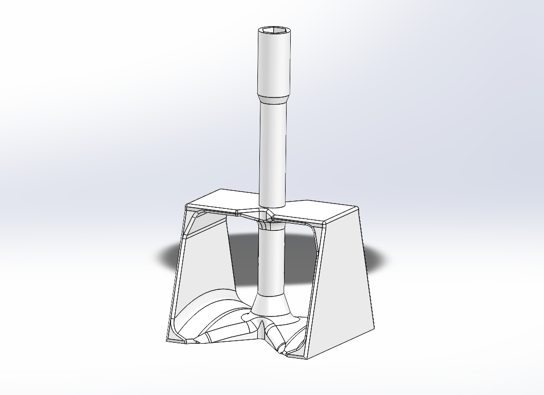
The curved bottom allows the fluid to pass over it, creating a high pressure zone above the curve, and a low pressure zone below the head, creting a small lifting effect on settled sediments. This also pulls the mixing head downwards with a small force, ensuring that the device remains secure. The vertical walls also serve to induce a vortex to further mix the solution. Though not as effective as the first version when mixing in a single direction, this new mixhead is able to mix in both directions and is more effective in churning the solution.
Electronics
This is the wiring diagram of the electronics in the device.
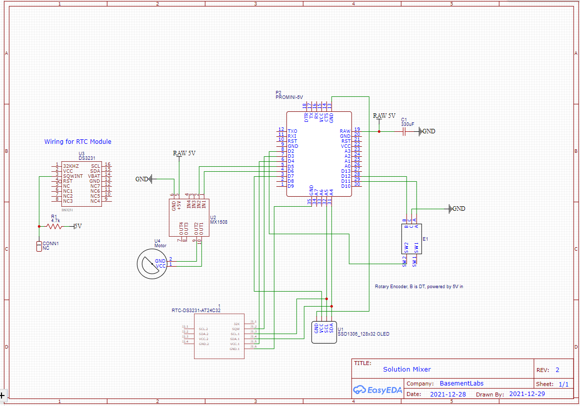
There are fewer overall components for this device. The through-hole resistors and transistors were deemed too bulky as they required a breadboard to be included in the device. The transistors were used in the first iteration mainly for power saving purposes, but it was deemed negligible compared to just switching digital pins on the Arduino itself. The resistors that were initially used for the encoder are now part of the breakout module the encoder is a part of as SMD’s.
To power the device, a 5V DC signal from the USB port is used. “High Power” components such as the motor driver, Arduino, and encoder were connected directly to the USB breakout board. Though not shown in the diagram, the encoder has an additional pin for VCC input. The “Low Power” RTC and display are connected to the Arduino for power. The display is connected to a digital pin being used as a switching power source. The maximum current draw for a digital pin is 40mA, but that display will draw no more than 30mA at peak operation. A capacitor was also added to smooth out current spikes during operation.
The button and RTC interrupt pins are connected to D2 and D3 respectively, as they are the Arduino’s interrupt-enabled pins. These are used to wake up the Arduino from sleep. The motor driver’s IN1 and IN2 are connected to D5 and D6 for the Arduino’s PWM capable pins. Note that the driver does not have additional “enable” pins, as the IN1/2 themselves enable the motor. This was another reason why this driver was chosen over other H-Bridges as it would save space.
The RTC module required some modification in order to achieve the desired functinality. The Raspberry Pi RTC breakout board only utilizes the I2C buses on the DS3231, but the INT/SQW pin on the IC was needed. The module provides an additional unused female header, which was where the INT/SQW pin was connected to in a voltae division circuit with a 4.7k resistor.
Software
The code can be found in this repository: https://github.com/ViktorVektor/DavidTankMixerTwo/blob/96e852c406bc31b08aba2f95c3dc9ad202b28758/David_Fish_Tank_Mixer_2_Final.ino
The primary changes made from v1 were the timed operations and mixing operations. Since the transistor was removed for the display, the switching function was instead done through software. EEPROM was also used in order to save values between power cycles.
For timed operations, the RTC provided its current time in seconds. When mixing, the desired time is calcualted in seconds and added to the start time. While mixing, the current time is compared with the end time, and will stop right away when that target time equals the current time. When sleeping, the Arduino prepares itself by turning off unecessary components like timers and the ADC to save power. It then takes the sleep time in seconds and calculates a wake up time, sending it to the RTC afterwards. The RTC is then configured to set an interrupt signal at the exact moment the target time is reached. The Arduino then goes to sleep and awaits the RTC’s signal. Note that in all operations, the RTC is constantly powered, be it by the internal battery or the 5V USB source.
In the mixing operations, control was changed to an H-Bridge PWM-based system. This allowed for rotation in either direction, so 2 more mixing modes were added. Churn 1 preiodically snaps back in the opposite direction, while Churn 2 turns in both directions in alternating intervals.
As per the feedback, the display is now always turned on even when asleep to indicate nominal operation.
When updating settings on the device, the Arduino’s EEPROM is accessed for this device. Due to the EEPROM’s relatively limited write/erase cycles, they are only updated if the value is changed by the user. Reading does not affect the EEPROM’s lifetime.
Other sections of the code facilitate the encoder, display, and main operations of the device. New menus were added for the mix speed and mix mode.
Future Revisions
In future revisions, I would like to try creating a custom PCB to further decrease the footprint of the device while still retaining its functionality. The display could also be upgraded to a 128x64 OLED. For the mixing head, proper fluid simulations would be preferred as it will give a better insight into which design is best before comitting to a physical prototype. Lastly, the nosie level of the device during operation could potentially be reduced by having a higher quality motor and gear assembly.
last edit: Jan 6 2022