5-Axis Robotic Arm
A 5-axis robot arm projet with the purpose of understanding the 3D printing process and microcontroller basics. This project also included calculation with inverse kinematics both by hand and through software in Python.
Software used
- Solidworks
- Fusion 360
- Pycharm (Python IDE)
- Arduino IDE (Arduino C++)
- Klipper/fluidd (3D Printing)
Hardware used
- Ender 3 (modified, see below)
- Various hand tools
Project Goals
The goal of the project was to get my feet wet with 3D modelling, 3D printing, hands-on electrical work, matrix calculations, and Python programming. A robotic arm would touch on all of these aspects and has plenty of information online for how it operates.
For the device, I set out a few requirements:
- Lift at least 500 grams
- Be mostly unconstrained in the motion of joints
- Be mostly 3D printed
- Operable though Python
September 2020
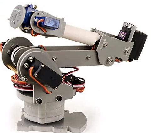
I was initially inspired by robotic arms using servo motors, particularly ones sold online or available on sites like Amazon. (https://www.amazon.ca/SainSmart-Control-Palletizing-Arduino-MEGA2560/dp/B00UMOSQCI). These arms are controlled with an arduino, moved by servo motors.
April 2021
Upon further reseasrch, I found that I preferred the motion achieved by industrial robots like the 6-axis Meca500 (https://youtu.be/lD2HQcxeNoA).
I started work on the mathematics behind how mechanical linkages would move, and eventually creating some software to help visualize how the robot arm would look. The end goal of this piece of software is to control the robot arm with Python, but the current state was more of an exercise in Python programming.
https://github.com/ViktorVektor/BasementRobot/blob/0fab545b65b477806c2f2ecbbd39898bb4239023/final%20main.py
In addition, I also explored communicating with an Arduino.
https://github.com/ViktorVektor/BasementRobot/blob/2452eb865f8f66fe7eb13dcaaa4190731e68ebba/gyro_servo_comm%20test.py
May 2021
Electrical
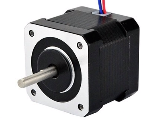
My research into the physical aspects of the arm started with the types of motor I would use. I knew I wanted more than 180 degrees of motion in a joint, so I started reading up on stepper motors. From my understanding, these types of motors would be used in places where precise position control and high torque is needed, while the weight of the motor itself not being a major consideration. My robot would not be operating in a speedy manner, so I decided on adopting the NEMA 17 and the 28BYJ-48 stepper motors. Both were very common and used the world over, so there was a lot of info and people talking about their experience with it online.
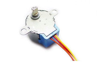
Being that the 28BYJ-28 was a unipolar stepper, I converted it to a bipolar motor by modifying some wiring. This had the added bonus of increasing the available torque of the small motor, but increases the likelihood of overheating. I had also planned to use an Arduino Mega 2560 and a RAMPS 1.4 shield to control the robot. This controller combination was typically used in DIY 3D printers, but can serve the a similar purpose in powering my motors. The stepepr drivers I would be using was the A4988 Bipolar Stepper Driver, one also commonly used with the RAMPS board.
3D Printing
My experience on 3D printing up to this point had been through one-off models and trinkets found online. After starting a position on a design team however, I wanted to further improve my skills in the whole FDM production process.
My current printer is Creality’s Ender 3. I chose it in the past due to its cost and community support. I also felt that this would be a good starting point for really getting to know the system worked, with all its limitations and potential issues. From the time I first purchased it back in October 2020, I had extensively modified it.
To start with, I had converted it to a Direct Drive extruder in order to work with very flexible filaments and TPU. Afterwards, I installed a bed levelling probe using a combination of an SG90 servo and a limit switch, as a cheaper alternative to dedicated bed levelling probes on the market. Soon after, I replaced the stock firmware with Marlin, an open-source 3D printing firmware. I learned more about how 3D printer firmware worked through looking at and modifying it for my printer.
After a few weeks on Marlin, I came across Klipper, a different kind of printer firmware. The main reason of existence of Klipper was to address the limits of microcontrollers by using a more powerfuly computer to process and direct the stepepr motors. A typical choice for computer is the Raspberry Pi. This allowed the printer to operate faster while retaining a similar print quality. This was great for the Ender 3 with its 8-bit microcontroller, and meant that I could prototype faster. It also included support for fluidd, which integrated a web gui with the Raspberry Pi. At the end of it all, I could now control my printer though my computer.
Some other physical modifications I did was to add a second Z-axis rod for better stability, and couplings using magnets on the z-axis rods due to them not being perfectly straight. I had also installed a better fan duct for the extruder head, now that I was printing at higher speeds.
Here is a great video on the topic. While I had lead screws, this person used ball screws: https://youtu.be/mqSQhwqSzvg
For the material of the robot, I opted to use Polylactic Acid (PLA) as the main structural material. This was due to its forgiving nature in printing and its availability. I had also been working with the material for some time now, so I was familiar with how it acted.
Robot Arm Part 1
For the arm itself, I had decided to use a 12:7:10 ratio for the Arm, Forearm, and Hand. Since I would be doing a 5-axis configuration, it would require 5 motors: One in the base, the shoulder, the elbow pitch, the wrist pitch, and the wrist rotation. I started work on the base of the robot.
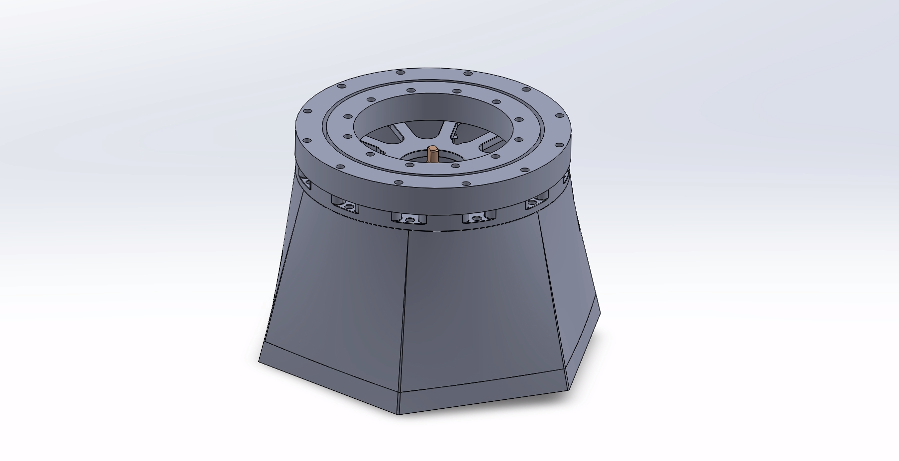
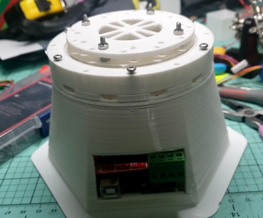
What I had come up with was a design that incorporated the motor into the base, which also had a slew bearing placed on the top of it. Wiring to the controller could be done via a hole in the back. I chose a slew bearing beacuse the base would be experiencing loads perpendicular to the top of the base. Since I did not have the tooling nor the funds to purchase such a bearing, I opted to 3D print one. I closely followed a tutorial here: https://www.thingiverse.com/thing:2375124. The RAMPS and a 28BYJ-48 motor was to be in the base initially, but later on the motor was upgraded to a NEMA-17 motor so there was no room for the controller.
The base of the robot:
After completing the base, work on the arm began. While only using the 28BYJ-48 stepper motors, each one was modified to be bipolar and ran at 12 volts. However, this did not provide enough torque since there was no gearing in place. The first design of the robot arm did not work so well, so an arm design using NEMA-17 motors and gear reducitons was devised.
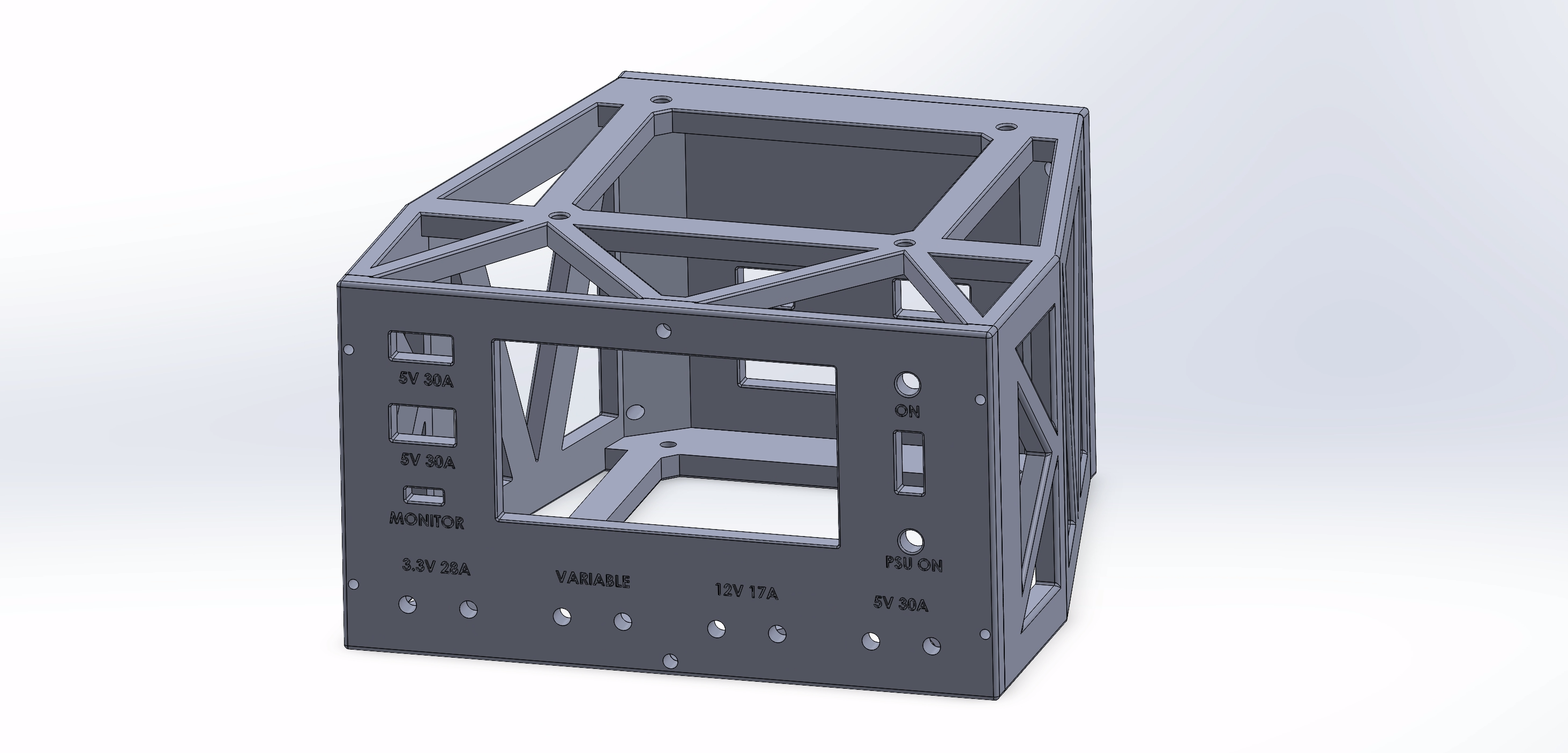
An additional issue I encountered was powering the RAMPS board and stepepr motors. The ramps board required at least 12V 5A to power the board and stepper drivers. At the time, I had insufficient means of powering it, so I converted an old desktop PC power supply into a benchtop power supply using some spare parts and a power meter.
June 2021
Robot Arm Part 2
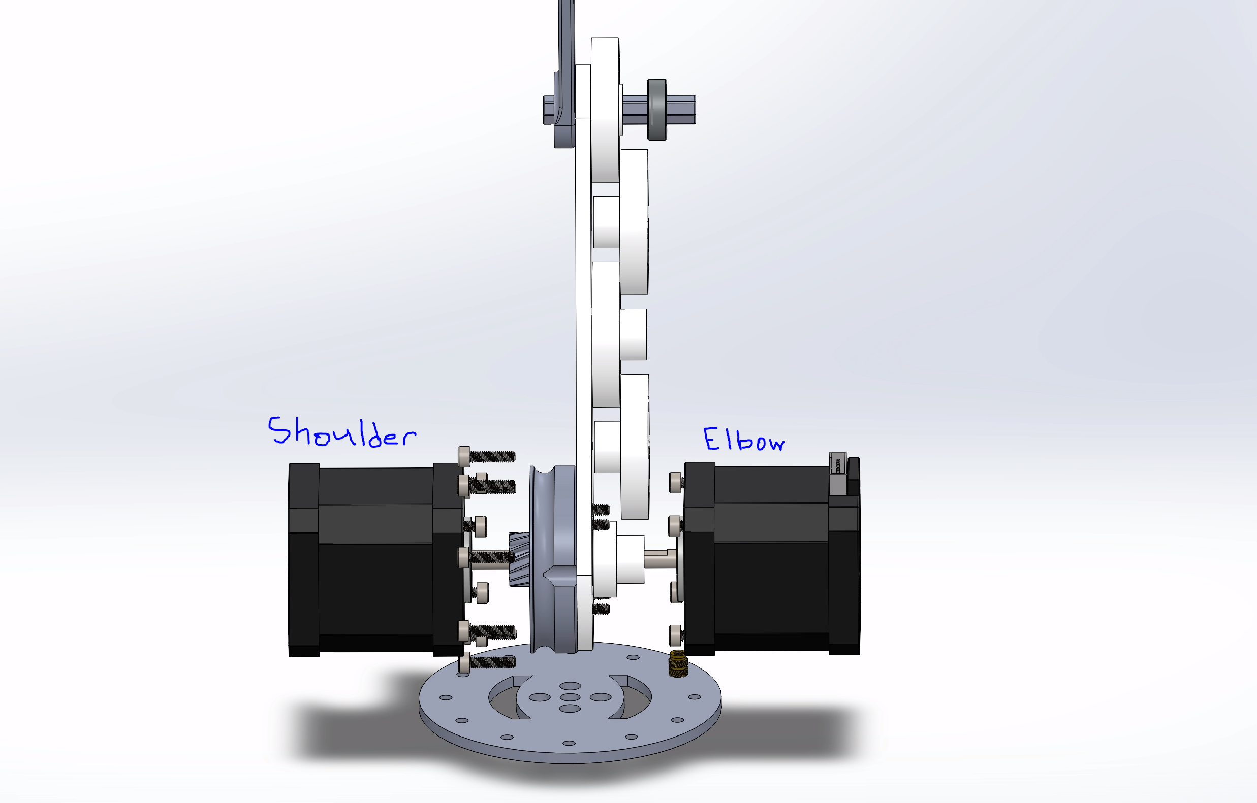
After experiences with the first model, I researched methods of increasing torque through mechanical means. I learned about planetery gearsets and compound pulleys being used in robotics. I found a helpful user demonstrating how one actuator they design functioned: https://www.thingiverse.com/thing:3293562. This design had a 38:1 ratio, allowing my robot to use a single stepper motor at the shoulder. Another method I learned about were compund pulleys, where a torque increase could be achieved over a distance: http://www.robotpark.com/academy/robotic-mechanisms-pulley-systems/ . This system could reduce the weight the shoulder stepper had to carry by moving the elbow stepper next to the base.
This was also exam season for summer courses so work was slow.
July 2021
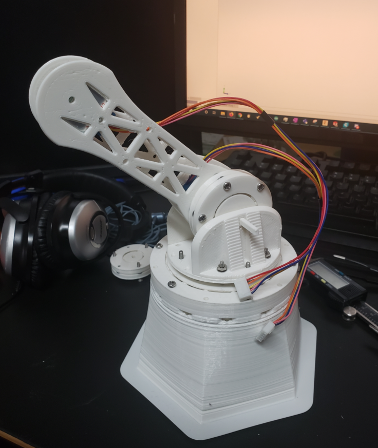
To implement the gearbox was fairly streightforward, but a few things needed to be considered beforehand. Since bigger motors were being used, the physical footprint of the robot needed to be increased, bringing with it more weight acting on the base. More torque than the first robot was needed to run it so joint friction needed to be reduced. At the shoulder where the first gearbox went, it needed to be strengthened so a wider and stronger housing was designed for it, fitting over the first robot’s base. Within the gearbox itself, PTFE lubricant was used along wih steel ball bearings.
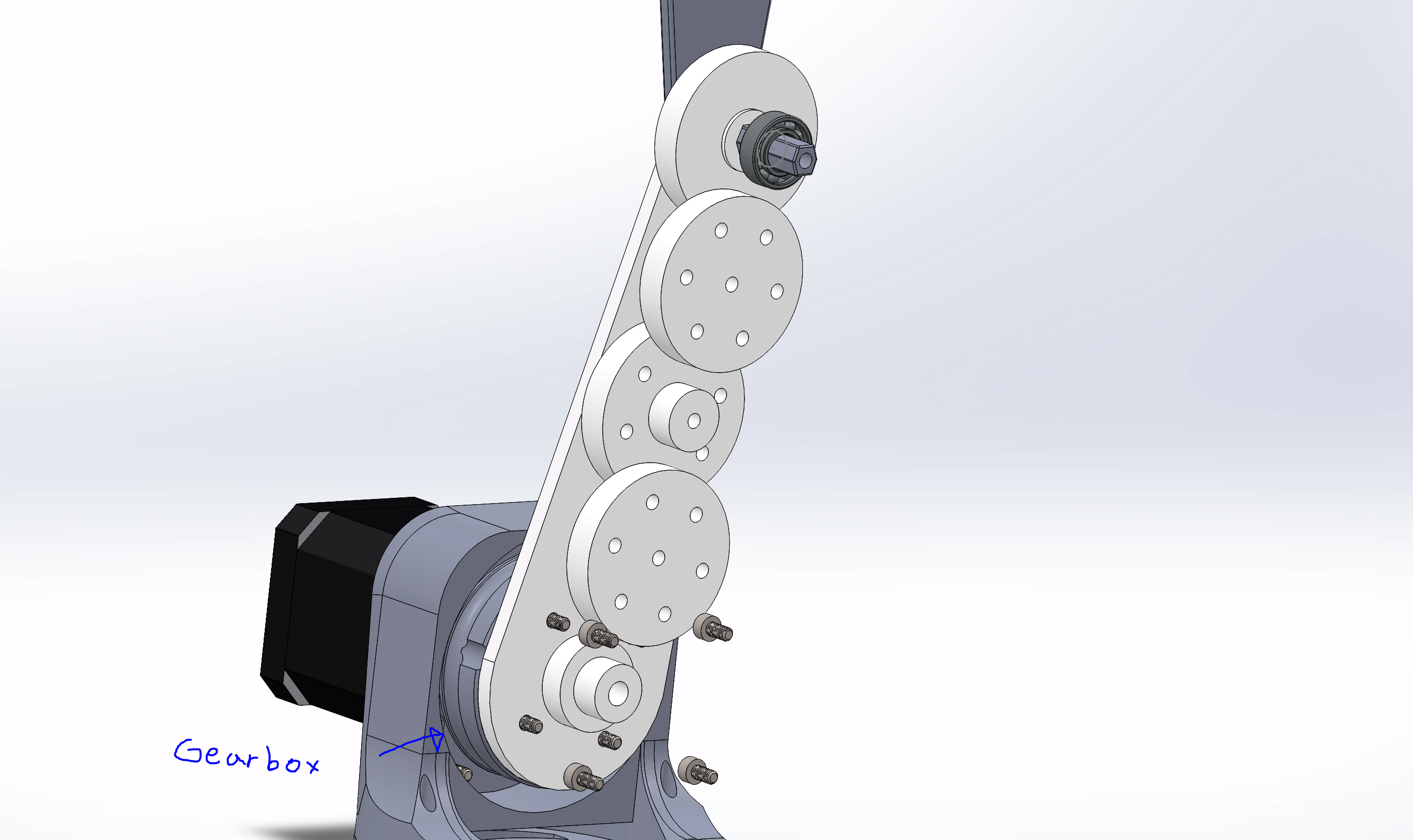
For the pulley system, the input sprocket would be placed concentric with the shoulder gearbox which then compounded along the interior of the arm. Each stage had a 1:3 ratio, for a total of about 12:1 at the output. The sprockets were made of PLA filament, while the belts were made of the flexible TPU filament. At the output, each side of the shaft was fitted with 688 Bearings on each side to reduce friction and support the concentrated loads.
I closely followed a tutorial for the sprockets here: https://www.thingiverse.com/thing:16627
The belts were followed from here: https://www.thingiverse.com/thing:2682637
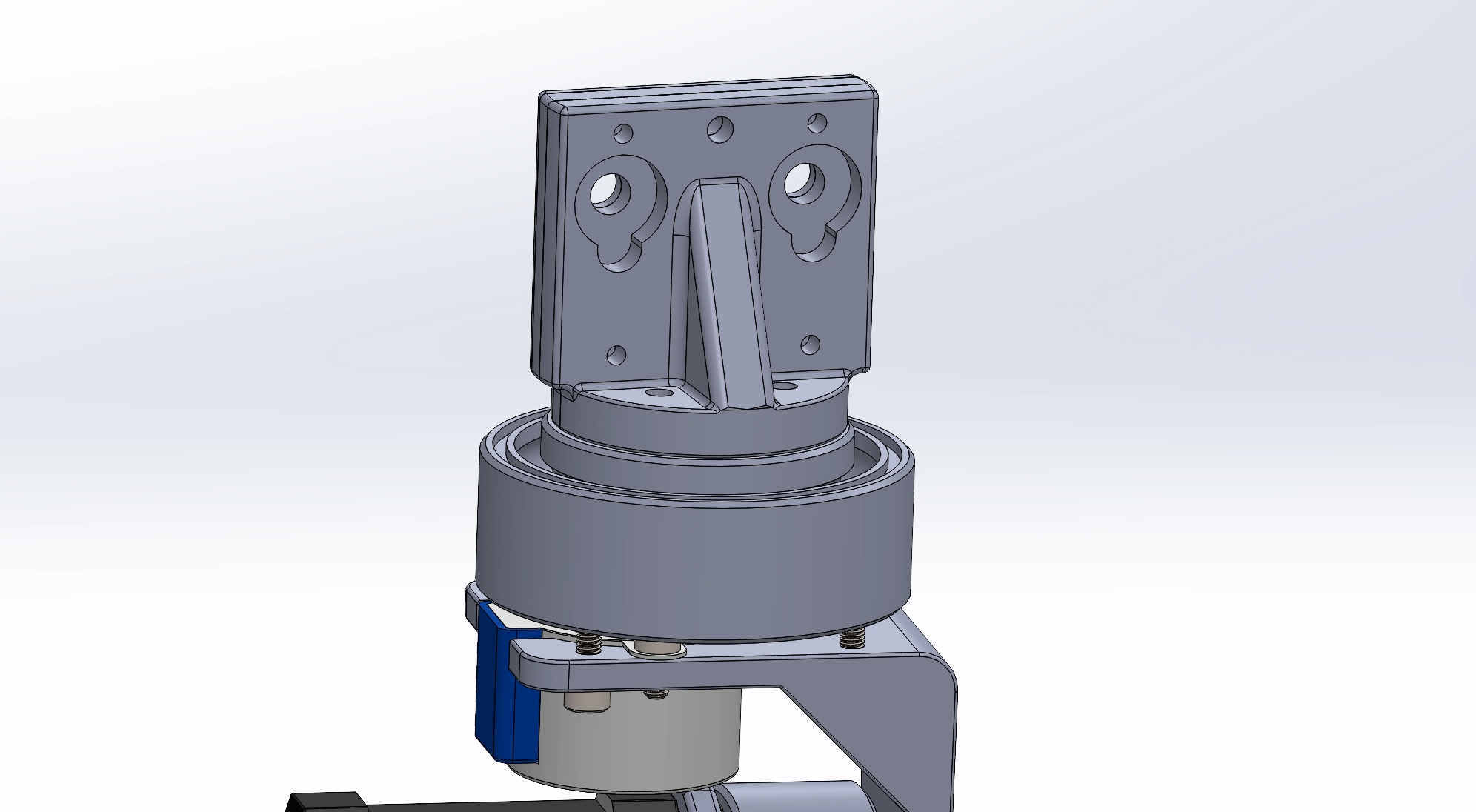
The wrist pitch stepper motor was also designed to use the gearbox, albeit a smaller version with the same gearing ratio. At this stage, the torque required is much less than at the shoulder, but the gearbox was already available from earlier print tests. The forearm would be connected to the pulley system’s output, which then carried the hand. PLA is quite stiff, so there was little flexing within the forearm even with all these attachments.
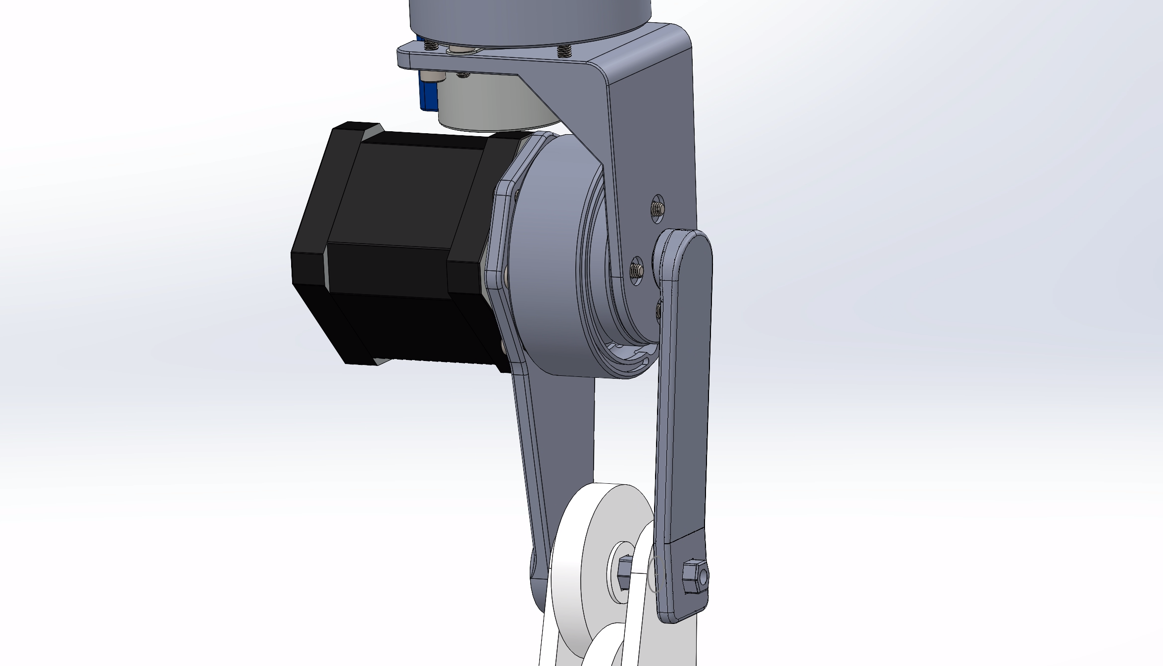
At the wrist, a smaller stepper motor would be used along with a gearbox, again available from previous testing. It will also have the end effector mount. This mount was designed to be swappable via a few screws. In its current configuration, it allows for 2 servo motors to be inserted for a simple claw.
With most of the main robot completed, parts were printed and assembled by about mid-July.
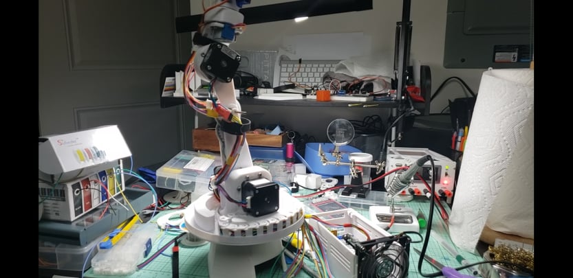
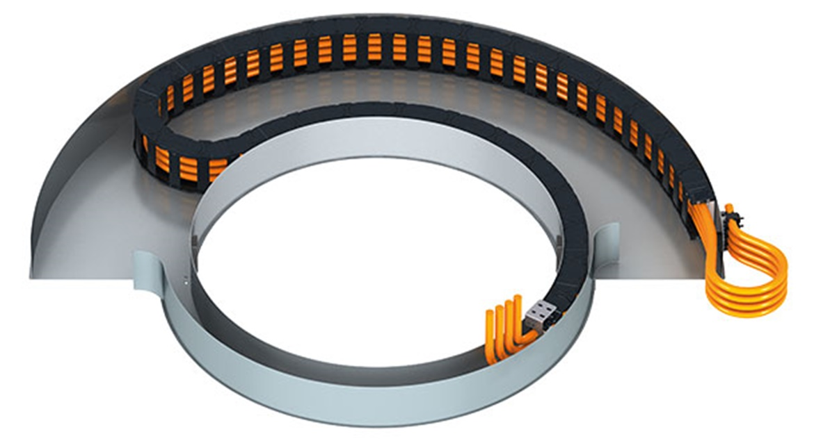
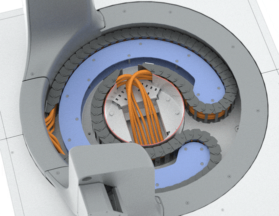
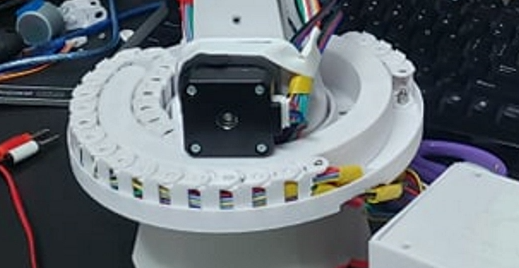
Cable Carrier
As can be seen in the first image of this webpage, the robot has a distinct disc near the base of the arm. This was the plate which contained the cabble carrier. This system allowed the robot to have about 440-degrees of rotation. It also helped the cabling remain secure and out of the robot’s path. This was partly inspured by both single and dual rotational cable carriers:https://www.andreasravn.com/double-360-cable-carrier
August 2021
With the elctricals completed, the next phase was to integrate the software created earlier in the year. Currently, this stage of the development is in progress as there are a few issues being sorted out, as well as time constraints due to personal matters.
Since the stepepr motors were configured to be in 1/16th step mode, the Arduino isn’t able to step multiple motors quickly enough. This is caused by both my inexperience with controlling high speed stepper motors, and the Arduino Mega’s limitations. In this configuration, the Arduino itself is processing during each step of the moro. I am hoping to find out about either a software or hardware solution to this issue. This also affects the auto-homing procedure I created, where it uses gyroscopes at its joints to determine stepper motor angles. Too many operations and not enough compute time made the system slow down to a crawl. However at this stage, I was able to test its weight lifting capabilities which met the goal.
The code for the Arduino can be found here, no Python integration yet: https://github.com/ViktorVektor/BasementRobot/blob/main/FG006_Robot_Arm.ino
Solidworks model of the bot:
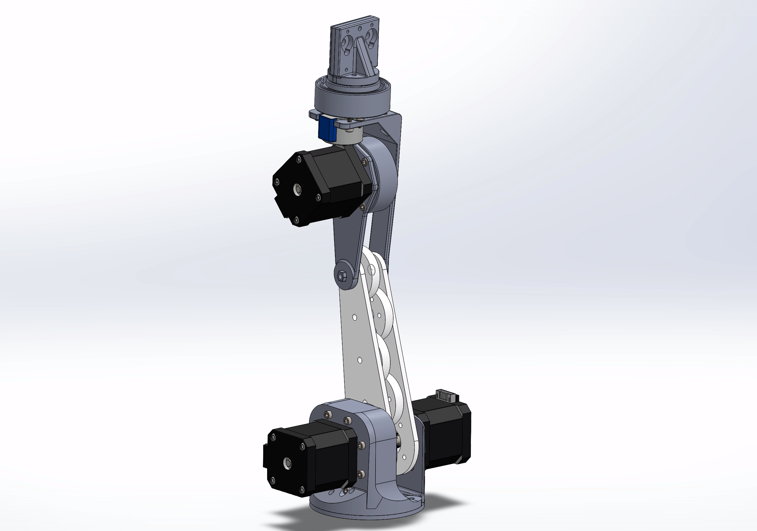
\\\\\\ To be continued